Motivation
I have a friend. Well, I have more than one, but I have a particularly peculiar friend. Now, according to both us and other friends, we’re both quite strange. Her birthday is coming up so I decided to make a particularly peculiar present to go along. For some reason only the DSM-5 or a priest could explain, she likes programming – particularly her TI-84 Plus CE calculator (the same model as one of my three Texas Instruments calculators). These calculators are programmed in BASIC, which is pretty neat. She also has basic knowledge in electronics and appears to want to learn more. Thus, combining these two I got the perfect idea for a birthday present.
A forgotten gem
For readers of the blog, you may know that I like the 8051 microcontroller, and some might even know that in around 1986 (as far as I could tell, from the datasheet’s release date) Intel released a version of the 8052 with a very powerful BASIC interpreter in ROM. Even though these were expensive at the time, they were meant for a wide audience and I’m surprised they didn’t catch on more – you basically had a Commodore 64 style BASIC terminal, with powerful math commands, GPIO, memory reading and writing, and wide expansion capabilities due to the 8052’s separate data and code spaces. With functions provided for everything one would want to do with an 8052 – full interrupts, PWM, timers, counters, a software DMA and even software error handling. All of this fit in a stock 8052’s ROM space and a minimal system can be made using three low-cost chips!
Simple and elegant design
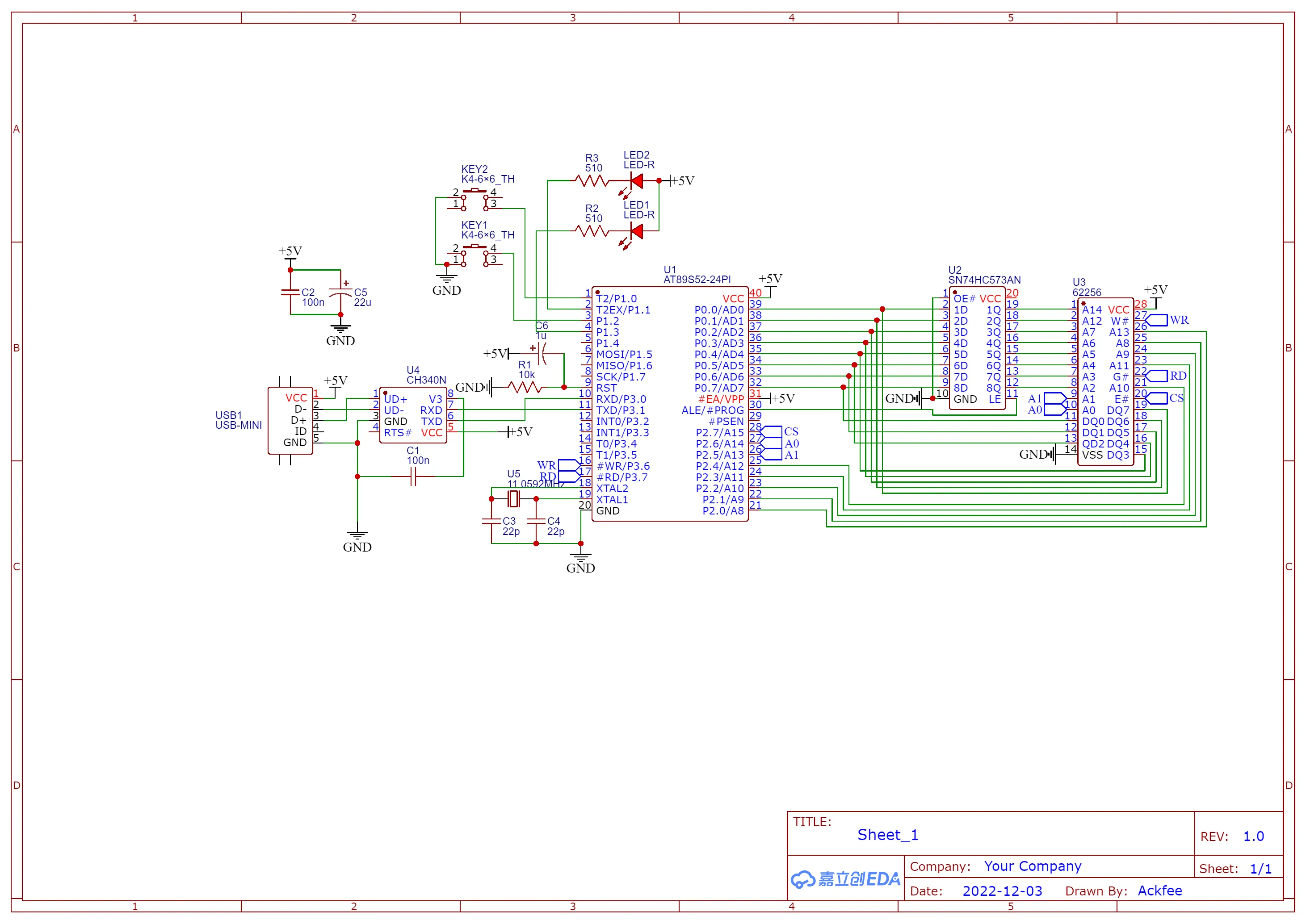
I decided to build one of these, since I had two 8052s on hand and I could source many more for cheap. I also needed to procrastinate on some schoolwork – senioritis is a real thing! Regardless, I had built 8052 computer systems before and knew exactly what to do and which latches to connect. I’ve grown to really like the 8052 and its elegance for the time, it’s a shame that Intel never developed their microcontroller business further, since the newer Intel microcontrollers based on x86 were also very cool before their discontinuation. The three chips required are an 8052 programmed with the BASIC ROM, an 8 bit latch (usually 74HC373 or 74HC573) and a Static RAM with a capacity larger than 2KB. I’m well stocked on all fronts, and played some videos while enjoying building the system on a perfboard – I didn’t even try to try the system on a breadboard, I was that confident that it would work.
Oh no
After around two hours of construction, I finished the build. I connected it to a USB-to-UART converter and… it didn’t work. The Intel manual said to press space when connecting it, and an auto-baud routine will detect the crystal and baud rate automatically using a clever routine. With an 11.0592MHz crystal, it can run at 115200 baud due to the 8052’s Timer2. I used a cheap Cypress FX2 USB logic analyzer to see what was going on. The UART didn’t function at all, so I returned to the manual. It said that before the UART is initialized, the 8052 test memory locations by writing and reading values, until it reaches an invalid address – if the microcontroller writes data and when reading it back it doesn’t read back what it wrote, no RAM is present there.
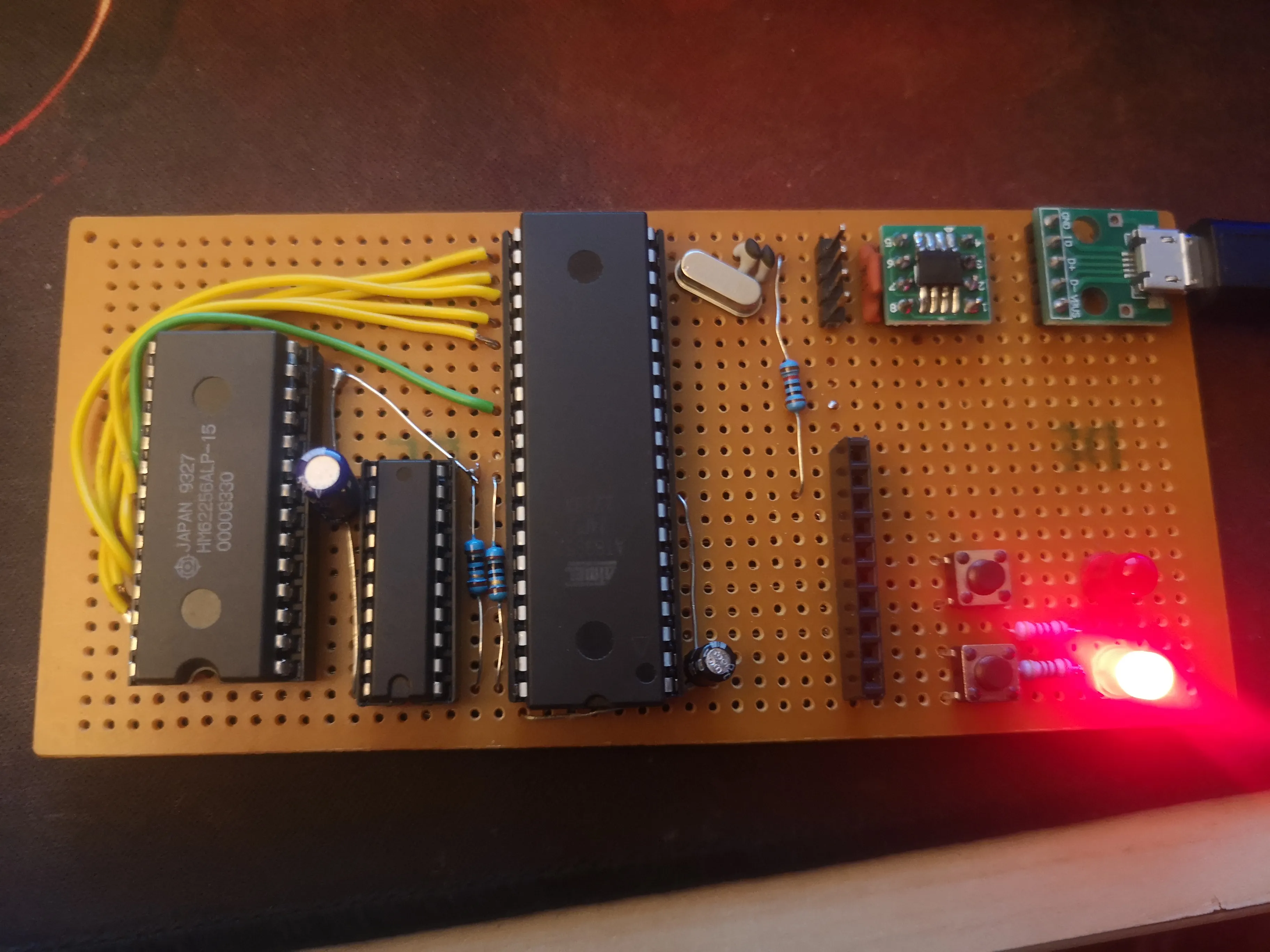
Since the 8052 didn’t respond to any writes, I then continued on with scoping the address and data lines, which gave a strange result – the writes did indeed work and the 32KB RAM was written to and read back properly. After an embarrassingly long time of troubleshooting, which included building a separate system on a breadboard, I discovered the issue. I socketed the SRAM, and the crappy socket didn’t touch the seventh data pin of the SRAM. D’oh! After pushing in the pin, everything worked. I’d say that I wasted a few hours, but I learned a bunch about troubleshooting and how to isolate problem areas through elimination and procedural testing. I started with checking the UART, then clocks, then read/write/chip select signals, then address and data pins, which narrowed down the issue to a physical connection, which I verified with a multimeter.
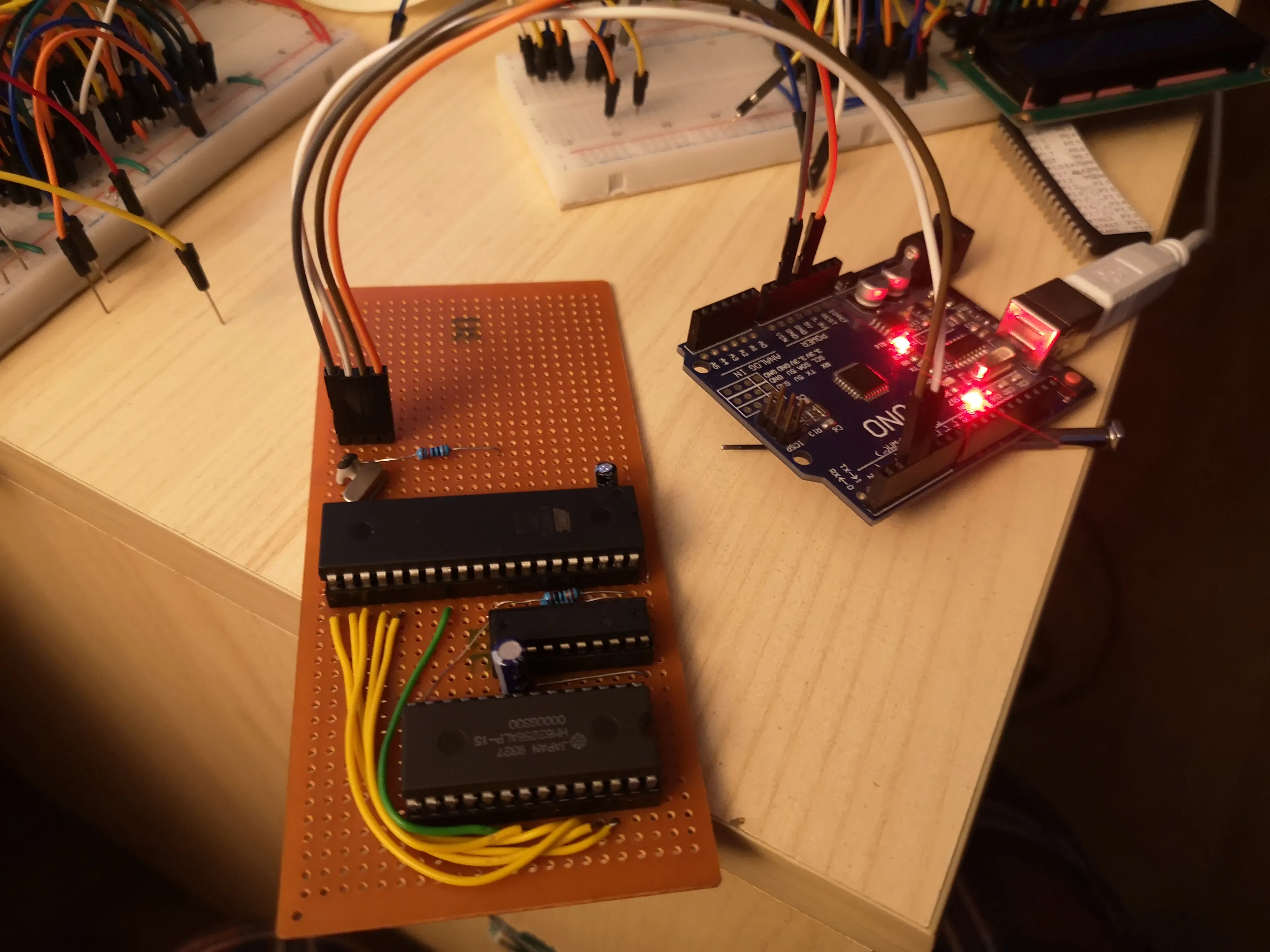
After I fixed this, I added two LEDs and two buttons to the free port on the 8052 which can be accessed through BASIC and some pin headers for connecting to a breadboard. Thus this became a development board as well as a basic computer. For the UART, to make it more permanent, I decided to salvage a dirt cheap CH340N USB-to-UART converter (requires only two external capacitors!), put it on a DIP adapter board and put a USB connector to it. I also put a 22uF capacitor as the main smoothing source. Despite the USB specification mandating a maximum of 10uF of capacitance on the USB line, since the wires I use for power are aluminium, they have a high enough resistance to resist the inrush current which the USB spec is afraid of. The real reason I used the 22uF capacitor is that it’s a really nice deep blue color. Yes, I am that shallow.
Some musings
Once everything was finished and working, I was surprised at just how cool what I had made was. I’ll probably build one of these myself in the future, but I’ll expand it significantly, mostly to add a programmable ROM, character display, expanded IO, sound, and everything else you would need to have a complete retro computer setup.
Regardless, I’ll give this one to my friend, she deserves it.